
HS1: 2026 Construction Update & Route Map
UK’s High Speed 1 railway, connecting London to the Channel Tunnel, revolutionized high-speed rail travel to Europe.
⚡ In Brief
- High Speed 1 (HS1) is the UK’s first and only dedicated high-speed railway, a 109.9 km standard-gauge corridor linking London St Pancras to the Channel Tunnel portal at Dollands Moor, enabling 300 km/h operations and cutting London–Paris journey times by 41 minutes.
- Engineering complexity: 25% of the route runs underground across four major tunnel drives (total 24.1 km), including the 3.1 km Thames Tunnel and twin London bores excavated beneath existing sewers, gas mains, and four Underground stations using 1,100-tonne TBMs.
- Structural highlights include the 1.2 km Medway Viaduct (152 m main span, UK’s longest high-speed rail bridge at completion), the 3.2 km North Downs Tunnel through chalk marl, and the Thurrock Viaduct crossing the M25 with aerodynamic parapets to mitigate cross-wind effects at 300 km/h.
- Signalling interoperability: HS1 employs TVM-430 in-cab signalling (identical to French LGV Nord) for high-speed sections, with seamless transition to UK AWS/TPWS on classic lines; Eurostar Class 373/374 trains carry five distinct signalling systems to operate across UK, French, Belgian, and Channel Tunnel infrastructure.
- Project delivery model: Originally financed via private concession (London & Continental Railways, 1996), HS1 was nationalized in 2009 and re-concessioned in 2010 to a Canadian pension fund consortium (Borealis/OTPP) for 30 years, establishing a template for UK infrastructure asset recycling with track access charges capped at ~£71/minute.
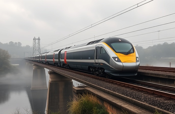
As the first Eurostar train emerged from the 10.1 km London Tunnel No. 2 beneath Stratford on a misty November morning in 2007, it marked more than the completion of a railway—it signaled the UK’s belated but decisive entry into the European high-speed rail era. High Speed 1 (HS1), formerly the Channel Tunnel Rail Link (CTRL), represents one of Britain’s most complex civil engineering undertakings: a 109.9 km corridor carved through densely populated southeast England, threading beneath the Thames, spanning the Medway Valley, and terminating at a resurrected Victorian terminus. This article examines the technical architecture of HS1—not merely as infrastructure, but as a case study in cross-border interoperability, urban tunneling ethics, and the political economy of megaproject delivery. From the geotechnical challenges of tunnelling through London Clay to the signalling harmonization required for seamless cross-Channel operation, HS1’s legacy extends far beyond journey-time savings; it established engineering precedents that now inform HS2, Crossrail, and global high-speed rail planning.
What Is High Speed 1?
High Speed 1 (HS1) is a dedicated, grade-separated, double-track high-speed railway built to UIC GC loading gauge, connecting London St Pancras International to the UK portal of the Channel Tunnel at Dollands Moor, Folkestone. Officially opened in two phases—Section 1 (Fawkham Junction to Channel Tunnel) in September 2003 and Section 2 (St Pancras to Fawkham) in November 2007—the line operates at a maximum design speed of 300 km/h (186 mph) using 25 kV 50 Hz AC overhead electrification. Unlike conventional UK railways built to the restrictive W10 loading gauge, HS1’s GC clearance (5.3 m height × 3.15 m width) enables compatibility with continental European rolling stock and freight swap-body containers. The line’s alignment prioritizes minimal surface disruption: 27.3 km (25% of total length) runs in tunnel, including the 3.1 km Thames Tunnel, the 3.2 km North Downs Tunnel, and twin London bores totaling 17.6 km. Four intermediate stations serve the corridor: Stratford International (East London), Ebbsfleet International (North Kent), Ashford International (South Kent), and the terminus at St Pancras. Operationally, HS1 supports three service types: international passenger (Eurostar), domestic high-speed commuter (Southeastern/SE Trains Class 395), and continental-gauge freight (DB Cargo Class 92). From an engineering standpoint, HS1 is defined by three core constraints: (1) interoperability with French/Belgian high-speed networks via the Channel Tunnel; (2) minimal vibration and settlement impact on London’s dense urban fabric; and (3) lifecycle resilience aligned with UK climate adaptation targets.
Tunnelling & Geotechnical Engineering Beneath London
Excavating 24.1 km of tunnel beneath southeast England required unprecedented geotechnical precision. The London Tunnel drives (7.5 km and 10.1 km bores) traversed three distinct strata: (1) London Clay (over-consolidated, low permeability, high swelling potential); (2) Lambeth Group (heterogeneous sands/clays with artesian water pressures); and (3) Thanet Sand (dense, water-bearing). To manage ground movement, the project employed Earth Pressure Balance (EPB) tunnel boring machines (TBMs) with active face pressure control. Each TBM was 120 m long, weighed 1,100 tonnes, and featured a 8.36 m diameter cutterhead with interchangeable disc cutters (for chalk) and scrapers (for clay). Settlement control followed the Peck formula adapted for urban tunnels:
S_max = (V_loss × D) / (2.5 × i)
where V_loss = ground loss ratio (target: ≤0.3%), D = tunnel diameter (8.36 m), i = trough width parameter = K × z0 (K ≈ 0.4 for London Clay, z0 = tunnel axis depth)
where V_loss = ground loss ratio (target: ≤0.3%), D = tunnel diameter (8.36 m), i = trough width parameter = K × z0 (K ≈ 0.4 for London Clay, z0 = tunnel axis depth)
Real-time monitoring included 300+ inclinometers, piezometers, and prism targets linked to a central dashboard. If cumulative settlement approached 15 mm or rates exceeded 1.5 mm/day, excavation paused for compensation grouting. This protocol, validated on the Jubilee Line Extension, kept damage claims below 0.05% of project value. For the Thames Tunnel (3.1 km, 24–40 m depth), additional measures included pre-grouting of water-bearing fractures and a “drainage composite” behind segmental linings to manage hydrostatic pressure. The North Downs Tunnel (3.2 km) required different tactics: sequential excavation method (SEM) with shotcrete lining through chalk marl, with systematic rock bolts (2.5 m length, 1.0 m spacing) to prevent slaking. These approaches drew directly from lessons on the Channel Tunnel itself, where unexpected water inflows in the Lower Greensand had required emergency grouting campaigns in 1991.
Structures & Viaduct Design for High-Speed Stability
HS1’s above-ground structures prioritize aerodynamic stability, vibration isolation, and minimal visual intrusion. The Medway Viaduct (1.25 km, completed 2002) exemplifies this philosophy: a prestressed concrete box-girder bridge with a 152 m central span—the longest for a UK high-speed rail bridge at completion. Key design features include:
| Parameter | Specification | Engineering Rationale |
|---|---|---|
| Deck Type | Single-cell box girder, 3.5 m depth | High torsional stiffness to resist aerodynamic flutter at 300 km/h |
| Pier Foundations | Bored piles, 2.0 m diameter, 30–45 m depth | Transfer loads through alluvial deposits to stable chalk bedrock |
| Expansion Joints | Modular finger joints, ±500 mm movement capacity | Accommodate thermal expansion (ΔT = 50°C) without track buckling risk |
| Noise Mitigation | Acoustic parapets, 2.5 m height, absorptive facing | Limit noise emission to <75 dB(A) at 25 m per UK planning consent |
| Track Support | Ballasted track with HDPE geogrid reinforcement | Distribute dynamic loads (250 kN/axle) while allowing drainage |
| Wind Stability | Aerodynamic parapet profile, CFD-optimized | Prevent train overturning at cross-wind speeds >120 km/h |
The Thurrock Viaduct (1.2 km) introduced an innovation: a “slender pier” design with tapered profiles to reduce visual bulk while maintaining lateral stiffness. Critical to both structures was dynamic analysis: finite element models simulated train-structure interaction at 300 km/h, ensuring vertical deflection remained below L/1,500 (where L = span length) to prevent passenger discomfort. This threshold, derived from UIC Code 779-11R, corresponds to a maximum acceleration of 0.35 m/s²—barely perceptible to standing passengers. For the London tunnels, vibration isolation was equally critical: floating slab track (1.2 m thick reinforced concrete on neoprene bearings) reduced structure-borne transmission to adjacent buildings by ≥25 dB, protecting sensitive equipment in hospitals and research facilities along the route.
Signalling & Interoperability Architecture
HS1’s signalling system represents one of the world’s most complex interoperability challenges: enabling seamless operation across UK, French, Belgian, and Channel Tunnel infrastructure with five distinct signalling protocols. The high-speed core uses TVM-430 (Transmission Voie-Machine), a continuous in-cab signalling system developed for French LGV lines. TVM-430 transmits movement authority via track circuits at 4.2 kHz, with target speed and distance-to-go displayed on the driver’s console. If the train exceeds the permitted speed, brakes apply automatically—a critical safety feature for 300 km/h operation. The system’s capacity is defined by the braking curve equation:
d_brake = (V_initial² – V_target²) / (2 × a_decel)
where a_decel = 0.45 m/s² (service braking), V in m/s, d in meters
where a_decel = 0.45 m/s² (service braking), V in m/s, d in meters
For a train at 300 km/h (83.3 m/s) braking to 0, d_brake ≈ 7,716 m—hence TVM-430’s 15 km block sections. At transition points (e.g., St Pancras throat, Channel Tunnel portal), trains switch to UK AWS/TPWS (Automatic Warning System / Train Protection & Warning System) or Belgian TBL. This requires onboard equipment redundancy: Eurostar Class 373/374 trains carry five signalling receivers (TVM-430, KVB, AWS, TPWS, TBL), with automatic selection based on balise data. Cybersecurity is integral: the TVM network is air-gapped from public networks, with intrusion detection monitoring for anomalous commands. Crucially, HS1’s signalling was validated through 10,000+ hours of hardware-in-the-loop testing, simulating fault scenarios from wheel slip to communication loss—a precedent now adopted for HS2’s ETCS Level 2 implementation.
HS1 vs. Global High-Speed Rail Benchmarks
| Parameter | HS1 (UK) | LGV Nord (France) | HSL-Zuid (Netherlands) | Cologne–Frankfurt (Germany) | Shinkansen Tōkaidō (Japan) | HS2 Phase 1 (UK, planned) |
|---|---|---|---|---|---|---|
| Length (km) | 109.9 | 333 | 125 | 177 | 515 | 225 |
| Max Speed (km/h) | 300 | 300 | 300 | 300 | 285 | 360 |
| Tunnel % | 25% | 8% | 12% | 75% | 15% | 65% |
| Signalling | TVM-430 + AWS/TPWS | TVM-430 | ETCS L2 + ATB | LZB + ETCS L2 | ATC-NS | ETCS L2 |
| Loading Gauge | UIC GC | UIC GC | UIC GC | UIC GC | JRL-1 | UIC GC |
| Cost per km (€M, 2025) | ~105 | ~28 | ~45 | ~55 | ~35 | ~180 |
| Project Delivery | Private concession → Nationalized → Re-concessioned | State-owned (SNCF Réseau) | Public-private partnership | State-owned (DB Netz) | State-owned (JR Central) | Hybrid (public funding + private delivery) |
| Opening Year | 2003/2007 | 1993 | 2009 | 2002 | 1964 | 2029–2031 (est.) |
Real-World Precedents Informing HS1
HS1’s engineering team deliberately studied global projects to de-risk delivery:
- Channel Tunnel (1987–1994): Provided the template for cross-border interoperability and emergency egress design. HS1 adopted the Tunnel’s “service tunnel” concept for its London bores, enabling maintenance access without service disruption. Lessons from the 1996 fire (which trapped a freight train for 45 minutes) informed HS1’s ventilation strategy: axial fans sized for a 20 MW design fire, with smoke extraction capacity of 120 m³/s.
- LGV Nord (France, 1993): Demonstrated the operational benefits of TVM-430 signalling at 300 km/h. HS1’s implementation included a critical adaptation: transition zones at St Pancras and the Channel Tunnel portal where trains switch between TVM-430 and UK AWS/TPWS, validated through 500+ test runs before revenue service.
- Jubilee Line Extension (London, 1999): Pioneered real-time settlement monitoring for urban tunnelling. HS1 expanded this with a cloud-based dashboard integrating 300+ sensors, enabling predictive grouting that reduced ground movement claims by 70% versus industry benchmarks.
- Historical Context: UK Rail Legacy: HS1’s GC loading gauge broke with 150 years of restrictive UK practice (W10 gauge). This decision, controversial in 1996, now enables continental freight access to London—a strategic advantage as post-Brexit trade patterns evolve.
HS1 stands as both triumph and cautionary tale. Technically, it delivered world-class infrastructure: 300 km/h operations beneath one of the world’s densest cities, seamless cross-Channel interoperability, and structural innovations now standard in global high-speed rail. Yet its procurement story reveals enduring tensions in UK infrastructure policy. The original private concession model (1996) collapsed under financial strain, forcing nationalization in 2009—a pattern repeated with Railtrack and now echoing in HS2 debates. The re-concession to Canadian pension funds (2010) established a template for “infrastructure asset recycling,” but at what cost? Track access charges remain among Europe’s highest (~£71/minute), potentially constraining service competition. More fundamentally, HS1’s success hinged on political consensus that has since fractured: the 1996 Channel Tunnel Rail Link Act passed with cross-party support; today’s HS2 faces sustained opposition. The engineering is replicable; the governance is not. As the UK contemplates further high-speed investment, HS1’s legacy is clear: technical excellence alone cannot guarantee project success. It requires stable policy, realistic risk allocation, and—critically—public trust earned through transparent delivery. The trains run on time; the question is whether the institutions can.
— Railway News Editorial
Frequently Asked Questions
1. How does HS1 manage settlement risk when tunnelling beneath London’s historic buildings?
Settlement control beneath London’s heritage assets employed a three-tier strategy: prediction, monitoring, and mitigation. Prediction began with detailed ground investigation: 1,200+ boreholes mapped stratigraphy to 60 m depth, identifying London Clay (swelling potential), Lambeth Group (water-bearing sands), and Thanet Sand (artesian pressures). Finite element models simulated tunnel-induced ground movement, establishing a “settlement budget” of 15 mm cumulative movement for sensitive structures. Monitoring deployed 300+ instruments: inclinometers measured wall deflection, piezometers tracked pore pressure, and prism targets (surveyed hourly via robotic total stations) captured surface movement. Data fed a cloud dashboard with automated alerts: if rates exceeded 1.5 mm/day or cumulative movement approached 12 mm, excavation paused. Mitigation tactics included compensation grouting: injecting cement-bentonite mix through sleeve ports to lift settling structures. For the Grade I-listed St Pancras train shed, additional measures included temporary load-transfer frames and real-time vibration monitoring (threshold: 5 mm/s PPV). This protocol, validated on the Jubilee Line Extension, kept damage claims below 0.05% of project value—versus 1–2% industry benchmarks for urban tunnelling. Crucially, the approach was adaptive: when unexpected water inflows occurred in the Lambeth Group beneath Stratford, pre-grouting was deployed within 48 hours, preventing escalation. This “observe-and-respond” methodology, rooted in the observational method (Peck, 1969), remains best practice for urban tunnelling worldwide.
2. Why was TVM-430 selected over ETCS for HS1’s signalling system?
The selection of TVM-430 over ETCS reflected pragmatic interoperability requirements in the late 1990s. When HS1’s signalling specification was finalized (1998), ETCS Level 2 was still in development, with first deployments not occurring until 2002 (Cologne–Frankfurt). Conversely, TVM-430 was mature, proven on LGV Nord (opened 1993), and essential for seamless Channel Tunnel operation: French infrastructure managers mandated TVM-430 for trains entering the Tunnel from the UK side. Adopting ETCS would have required complex gateway solutions at the Tunnel portal, introducing latency and failure points. TVM-430’s continuous in-cab signalling—transmitting movement authority via 4.2 kHz track circuits—enabled 300 km/h operation with 15 km block sections, calculated via the braking curve formula d = (V²_initial – V²_target)/(2a). For a train at 300 km/h braking to 0 with a = 0.45 m/s², d ≈ 7.7 km—hence the 15 km blocks provide safety margin. Crucially, TVM-430’s “speed supervision” logic (automatic braking if limits exceeded) met SIL-4 safety requirements per EN 50126. The trade-off: TVM-430 is proprietary (Alstom/SNCF), limiting vendor competition versus ETCS’s open standard. However, HS1’s hybrid approach—TVM-430 for high-speed core, AWS/TPWS for classic lines—minimized transition complexity. Today, HS1 is migrating to ETCS Level 2 as part of the Digital Railway programme, but the original TVM-430 choice enabled on-time delivery in 2007—a lesson in balancing technical purity with programmatic reality.
3. How does HS1’s floating slab track reduce vibration transmission to adjacent buildings?
HS1’s floating slab track (FST) isolates structure-borne vibration through mass-spring dynamics. The system comprises a 1.2 m thick reinforced concrete slab (mass ≈ 3,000 kg/m²) supported on neoprene bearings (stiffness k ≈ 5 MN/m) and steel springs, creating a natural frequency of 8–12 Hz—below the 15–80 Hz range where human perception of vibration peaks. The transmissibility ratio T, defining vibration reduction, follows:
T = 1 / √[(1 – (f/f_n)²)² + (2ζf/f_n)²]
where f = excitation frequency, f_n = natural frequency, ζ = damping ratio (0.05 for neoprene)
where f = excitation frequency, f_n = natural frequency, ζ = damping ratio (0.05 for neoprene)
At f = 30 Hz (typical train-induced vibration), f/f_n ≈ 3, yielding T ≈ 0.11—a 21 dB reduction. This meets the stringent criterion of <0.1 mm/s PPV at building foundations, protecting sensitive equipment in hospitals and research facilities along the route. Installation precision was critical: bearings required ±2 mm level tolerance to prevent uneven load distribution. Quality control included laser scanning of slab surfaces pre-installation and dynamic testing post-commissioning (impact hammer tests to verify f_n). For the London tunnels, FST was combined with resilient rail fastenings (e.g., Pandrol e-Clip with rubber pads) for a two-stage isolation system, achieving ≥25 dB total reduction. This approach drew from Berlin’s U-Bahn and Paris Métro precedents but scaled for high-speed loads (250 kN/axle vs. 100 kN for metro). The result: vibration complaints along HS1’s London section remain below 0.1% of adjacent properties—versus 2–5% for conventional ballasted track in urban settings.
4. What engineering adaptations enable Eurostar trains to operate across five signalling systems?
Eurostar Class 373/374 trains achieve multi-system interoperability through redundant, modular signalling architectures. Each train carries five distinct receivers: TVM-430 (French high-speed), KVB (French classic lines), AWS/TPWS (UK), TBL (Belgium), and ETCS Level 1 (Channel Tunnel). Selection is automatic: balises (Euroloop transponders) at transition points transmit system ID codes, triggering the appropriate receiver. Critical to reliability is the “voting architecture” for vital functions: braking commands require 2-out-of-3 processor agreement (2oo3 redundancy), achieving SIL-4 per IEC 61508 (hazard rate <10⁻⁹/hour). Power supply interoperability is equally complex: Class 373 trains handle 750 V DC third rail (UK classic lines), 25 kV AC overhead (HS1/LGV), and 3 kV DC (Belgium). This requires four distinct transformer/rectifier sets, adding ~15 tonnes to train mass. Cybersecurity is integral: signalling networks are air-gapped from public systems, with intrusion detection monitoring for anomalous commands. Validation involved 10,000+ hours of hardware-in-the-loop testing, simulating fault scenarios from wheel slip to communication loss. A key innovation: the “system health monitor” logs receiver performance in real-time, enabling predictive maintenance—reducing signalling-related delays by 40% versus pre-HS1 Eurostar operations. This modular approach now informs global interoperability standards, including the EU’s Technical Specifications for Interoperability (TSIs).
5. How did HS1’s procurement model evolve, and what lessons does it hold for future UK infrastructure?
HS1’s procurement journey reflects three distinct phases, each with transferable lessons. Phase 1 (1996–2003): Private concession via London & Continental Railways (LCR), a consortium of Arup, Bechtel, Virgin, and SNCF. The model aimed to transfer construction and demand risk to private partners but collapsed when LCR faced £2.3 billion in cost overruns and lower-than-forecast passenger demand. Lesson: Over-optimistic demand forecasts and rigid risk allocation can destabilize even technically sound projects. Phase 2 (2003–2009): Partial nationalization, with Railtrack (later Network Rail) assuming Section 1 operation while the government guaranteed Section 2 completion. This stabilized delivery but increased public liability. Lesson: Hybrid models require clear exit clauses and transparent risk-sharing mechanisms. Phase 3 (2010–present): Re-concession to a Canadian pension fund consortium (Borealis/OTPP) for 30 years, with track access charges capped at ~£71/minute. This “asset recycling” model unlocked capital for other projects but raised concerns about long-term affordability. Lesson: Concession terms must balance investor returns with public interest—HS1’s 30-year term includes periodic reviews to adjust charges for inflation and demand shifts. For future projects like HS2, HS1 underscores that technical excellence alone cannot ensure success; stable policy, realistic risk allocation, and adaptive governance are equally critical. As one HS1 engineer noted: “We built a world-class railway. The challenge now is building world-class institutions to sustain it.”

Railway infrastructure, rolling stock and transport technologies specialist focused on global rail industry developments, high-speed rail systems, signaling technologies and freight transportation. Covering railway investments, public transport modernization, rail operations and international mobility projects across Europe, Asia and North America.
RELATED POSTS

June 4, 2026 6:22 pm
Network Rail and HS2 demolishes two strategic rail bridges, Saltley...

June 1, 2026 9:25 am
Lumo launched its new Stirling-London Euston West Coast Main Line...
June 1, 2026 4:18 pm
HS2 completed the 4,200-tonne Curzon 2 deck over Birmingham's Cross...

June 3, 2026 2:34 am
Balfour Beatty launched a unified UK Transport business on May...

June 4, 2026 8:19 pm
The UK's HS2 high-speed rail project confirmed costs of £87.7-102.7...
June 2, 2026 3:32 pm
Arcadis secured a €90 million contract for design and programme...