
What is a Railway Switch (Turnout)? How Trains Change Tracks
The humble railway switch is arguably the most underappreciated component in railway infrastructure.
⚡ In Brief
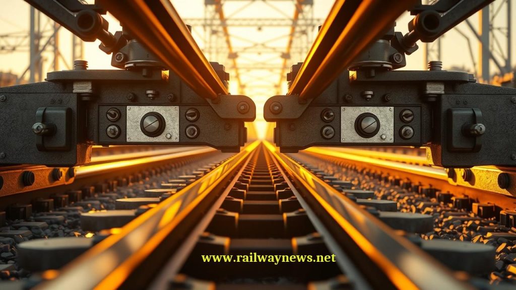
- A railway switch (UK: points; US: turnout) is a mechanical assembly that guides a train from one track to another by moving a pair of tapered switch rails against fixed stock rails.
- The frog (crossing) is the critical point where the two rail paths cross — a gap in the rail that every wheel must pass over, and the primary source of noise, vibration, and wear in any switch.
- Standard switches limit diverging speed to 30–80 km/h; high-speed switches with movable point frogs allow diverging speeds of 100–160 km/h and straight-through speeds of 300+ km/h.
- A single high-speed switch on a mainline can cost €500,000–€1.5 million and weigh over 50 tonnes — they are among the most expensive and safety-critical individual components in railway infrastructure.
- Switch failure is one of the leading causes of railway delays: in Europe, points failures account for approximately 10–15% of all infrastructure-related delays on busy networks.
On 3 June 1998, the Eschede ICE disaster killed 101 people — the deadliest high-speed rail accident in history. The immediate cause was a fractured wheel tyre. But the mechanism of catastrophe was a railway switch: the derailed wheel struck the frog of a switch at 200 km/h, causing the entire switch assembly to be lifted and flipped onto a road bridge above the track. The bridge collapsed onto the passing train.
Switches are among the most mechanically complex and safety-critical components in railway infrastructure. Every train movement through a junction, every entry into a station, every crossing of a parallel track depends on a switch working correctly. Understanding how switches work — and why high-speed switches are so different from conventional ones — is fundamental to understanding railway operations and the engineering challenges of high-speed rail.
What Is a Railway Switch?
A railway switch is a mechanical installation that enables a train to be guided from one track to another. Unlike road vehicles, trains cannot steer — their flanged wheels follow the rails. The only way to change a train’s direction is to change the track itself.
A switch achieves this by incorporating a pair of movable switch rails (also called point rails or blades) that can be positioned against either of two fixed stock rails. In one position, the switch rails guide the wheel flange straight ahead onto the main line. In the other, they divert the train onto a diverging track. The switch is operated remotely by a point motor (electric or hydraulic actuator) connected to the interlocking system.
Key Components of a Railway Switch
| Component | Function | Notes |
|---|---|---|
| Switch rails (blades) | Movable tapered rails that guide the wheel flange | Move laterally 100–160 mm between positions; must seat tightly against stock rail |
| Stock rails | Fixed outer rails against which switch rails rest | Must be straight and free of burrs; tight contact with switch rail is safety-critical |
| Point motor (actuator) | Moves and locks switch rails in position | Electric (most common), hydraulic (high-speed switches); confirms position to interlocking |
| Stretcher bars | Connect the two switch rails to move them simultaneously | Multiple bars ensure rails move together and maintain gauge |
| The frog (crossing) | The intersection where two rail paths physically cross | Fixed or movable; contains a gap that every wheel must pass over |
| Guard rails (check rails) | Guides wheel through the frog gap safely | Positioned opposite the frog to constrain wheel path |
| Closure rails | Connect switch rails to the frog | Fixed curved or straight rails bridging switch and crossing |
| Switch heating | Prevents ice and snow from jamming switch rails | Electric or gas heating; critical on exposed mainline switches in cold climates |
The Frog: The Most Critical Component
The frog — named for its resemblance to a frog’s foot — is the crossing point where two rails intersect. It is the most mechanically challenging part of any switch, and the primary source of noise, vibration, and maintenance cost.
The problem is geometric: at the crossing point, one rail must cross the other. This creates a gap in each rail where the crossing rail passes through. Every wheel travelling over the frog must cross this gap — a moment when the wheel tread loses rail support and drops slightly before the wheel flange or the opposite rail picks it up again. This gap creates impact, vibration, and wear, and is the reason switches have speed restrictions on the diverging route.
The frog angle — expressed as a ratio (1:9, 1:15, 1:65) — describes the geometry of the divergence. A 1:9 frog has a relatively sharp divergence angle (suitable for low-speed yard work); a 1:65 frog has a very shallow angle (used on high-speed lines for gentle divergence at high speed). The larger the second number, the longer the switch and the higher the permitted speed.
Fixed Frog vs Movable Point Frog: The High-Speed Solution
| Parameter | Fixed (Rigid) Frog | Movable Point Frog (Swing Nose) |
|---|---|---|
| Gap at crossing point | Always present — wheel drops through gap | Gap closed by moving nose — continuous rail surface |
| Max diverging speed | 30–80 km/h (depending on frog angle) | 100–160 km/h |
| Max straight-through speed | 160–200 km/h (vibration limits) | 300–350+ km/h |
| Ride quality | Impact/vibration as wheel crosses gap | Smooth — no gap in running direction |
| Maintenance complexity | Lower | Higher — additional moving part with tight tolerances |
| Cost | €50,000–€200,000 | €500,000–€1.5 million |
| Typical use | Conventional lines, yards, depots | All high-speed lines; busy mainlines above 200 km/h |
Switch Types: A Complete Guide
| Type | Description | Typical Speed | Typical Use |
|---|---|---|---|
| Simple turnout | One track diverging from another | Straight: line speed; diverge: 30–80 km/h | Most common; junctions, sidings, loops |
| Symmetrical (Y) turnout | Both routes diverge equally from centre | Equal speed in both directions | Triangles, reversing moves |
| Three-way turnout | One track splitting into three simultaneously | Lower speed; complex geometry | Depots, yards with space constraints |
| Crossover | Two turnouts connecting parallel tracks | Typically 40–80 km/h | Allowing trains to cross between adjacent tracks |
| Scissor crossover | Two crossovers in opposite directions forming an X | Typically 30–60 km/h | Stations; enables flexible platform allocation |
| Diamond crossing | Two tracks crossing at an angle; no route transfer | Line speed (straight through only) | Flat grade crossings; tram/rail intersections |
| Single slip | Diamond with one additional route connection | Low speed | Space-constrained junctions |
| Double slip | Diamond with route connections in both directions | Low speed; very complex | Dense urban terminals; metros |
The Frog Number: Understanding Switch Geometry
The frog number (also called the crossing number or turnout ratio) is the key parameter describing switch geometry. It is expressed as 1:N, where N is the cotangent of the crossing angle — the number of units of straight travel for every unit of lateral divergence.
| Frog Number | Diverging Angle | Switch Length (approx.) | Max Diverging Speed | Typical Application |
|---|---|---|---|---|
| 1:7 – 1:9 | 6.3° – 8.1° | 15–20 m | 30–40 km/h | Yards, sidings, depots |
| 1:12 – 1:15 | 3.8° – 4.8° | 30–40 m | 60–80 km/h | Conventional mainlines, stations |
| 1:18.5 – 1:26 | 2.2° – 3.1° | 60–100 m | 100–130 km/h | High-speed approach, busy mainlines |
| 1:46.3 – 1:65 | 0.9° – 1.2° | 100–200+ m | 160 km/h (with movable frog) | High-speed lines (TGV, ICE, AVE) |
How Points Failures Cause Delays
Switch failures are one of the most common causes of railway delays. A single failed switch at a busy junction can block multiple routes simultaneously, since many trains share the same switch for different movements. The failure modes include:
- Detection failure: The point motor moves the switch rails, but the detection circuit does not confirm that the rails have seated correctly against the stock rail. The interlocking prevents any train movement over the switch until the fault is cleared.
- Mechanical jam: Ice, debris, or a foreign object prevents the switch rails from moving to the correct position. In winter, switch heating failures are a major operational risk.
- Broken switch rail: A fatigue fracture or impact damage to a switch rail requires immediate possession and rail replacement — typically a multi-hour process.
- Motor failure: The point motor fails mechanically or electrically, requiring either emergency manual operation or motor replacement.
On high-density networks, a single switch failure at a major junction can affect dozens of trains per hour. Network Rail estimates that points failures account for approximately 14% of all infrastructure-related delay minutes on the UK network — a disproportionate impact for components that represent a small fraction of total track infrastructure.
Smart Switches: Digital Monitoring and Predictive Maintenance
The traditional approach to switch maintenance is time-based: inspect at fixed intervals, replace components on a schedule. Modern railway operators are shifting to condition-based maintenance using embedded sensors that monitor switch health continuously:
- Current signature analysis: The electrical current drawn by the point motor as it operates forms a characteristic signature. Changes in this signature — increased current indicating increased resistance, or abnormal timing — can detect developing mechanical problems before failure.
- Force measurement: Strain gauges on stretcher bars measure the force required to operate the switch, detecting early signs of rail distortion or debris accumulation.
- Temperature monitoring: Sensors detect heating system failures before they cause icing problems.
- Vibration analysis: Accelerometers on switch components detect unusual vibration signatures that may indicate loose fastenings or component wear.
Siemens Mobility’s Simis IS and Alstom’s SmartLock systems, among others, integrate these sensor streams with predictive algorithms to identify switches at elevated failure risk, enabling proactive intervention during planned possessions rather than reactive response to failures during traffic hours.
Editor’s Analysis
The humble railway switch is arguably the most underappreciated component in railway infrastructure. It is everywhere — a busy station might have hundreds of them — yet it receives a fraction of the engineering attention lavished on rolling stock or signalling systems. The 14% share of infrastructure delays attributable to switch failures is a policy failure as much as an engineering one: many legacy switches on busy networks are decades old, operating beyond their designed lifespan on increased traffic loads, monitored by inspection regimes that were designed for a different era. The transition to condition-based maintenance using current signature analysis and force monitoring is the right direction, and the technology is mature — the barrier is investment in the data infrastructure to collect and act on sensor data at scale across tens of thousands of switches. High-speed switch technology has largely solved the speed problem: 1:65 switches with movable frogs allow 160 km/h diverging speeds that were unimaginable 30 years ago. The frontier now is reliability: a high-speed switch costs over €1 million and a failure blocks a €500 million per year railway. The economics of predictive monitoring at that price point are compelling, and every major infrastructure manager is moving in this direction. The question is pace. — Railway News Editorial
Frequently Asked Questions
- Q: What is the difference between “points,” “switch,” and “turnout”?
- These are regional terms for the same component. “Points” is the standard British English term, used by Network Rail and throughout the UK rail industry. “Switch” is used in both British and American English to describe the movable rails specifically, but is also used informally to refer to the complete assembly. “Turnout” is the standard North American term for the complete assembly including switch rails, closure rails, and frog. In European standards and international rail engineering, “switch” and “turnout” are both used, with “switch” often referring to the blade/rail portion and “turnout” to the complete installation.
- Q: Why do trains slow down through switches?
- Trains slow down on the diverging route through a switch for two reasons. First, the curved geometry of the diverging path imposes a lateral acceleration on passengers and cargo — faster speeds through the curve create greater discomfort and higher wheel-rail forces. Second, the frog gap creates an impact as each wheel drops briefly into the gap, and at higher speeds this impact is more severe, increasing wear and the risk of derailment. High-speed switches with movable frogs address the second issue by eliminating the gap, but the first issue — the curve geometry — still limits diverging speed regardless of frog type.
- Q: What is a derailment switch and why is it used?
- A derailment switch (also called a catch switch or trap point) is a deliberately designed safety device that causes a runaway or unauthorised vehicle to derail in a controlled manner before it can enter a main line or collision with another train. They are placed at the end of sidings, on gradients where a vehicle could roll away, and at the entrance to occupied platforms. The derailment switch is normally set to the derailing position and must be positively set to “safe” before any authorised movement. If a vehicle runs away without authorisation, it strikes the derailment switch and is guided off the track at low speed into a sand drag or buffer stop — a controlled derailment that prevents a potentially catastrophic main line collision.
- Q: How are switches operated and who controls them?
- Most mainline switches are operated remotely by the signaller (train controller) via the interlocking system — a safety system that ensures switches are correctly set and locked before a signal is cleared for a train to proceed. The interlocking prevents conflicting routes from being set simultaneously. Point motors (electric or hydraulic actuators) physically move the switch rails and send electrical confirmation back to the interlocking when the rails are correctly seated. On some secondary lines and depots, switches may still be operated manually by a trackside lever, but this is increasingly rare on mainline infrastructure.
- Q: What happens if a switch is set against a moving train?
- If a switch is moved while a train is passing over it — an event called “running through” or “splitting the points” — the results depend on speed and the type of switch. At low speeds, the train may continue through without derailing if the switch rails are not moved far enough to deflect the wheels. At higher speeds, the wheel flange may be caught by the moving rail and deflected off the track, causing a derailment. Modern interlocking systems prevent this by locking switches in position during route occupancy and by detecting train presence on the switch before allowing any movement. “Run-through” derailments are rare on signalled mainlines but can occur in depots or on unsignalled sidings.
RELATED POSTS
April 1, 2026 8:45 am
Renfe Alquiler finalized a 15-year lease for ex-DB coaches with...
April 1, 2026 12:10 pm
Alstom secured a €410 million contract from CFR SA to...
April 1, 2026 2:14 pm
Saudi Arabia Railways launched a 1,700 km freight rail corridor...
April 1, 2026 8:40 pm
BNSF Railway expands Galesburg, Illinois, yard capacity, with second hump...
April 1, 2026 4:31 pm
Network Rail upgraded Berrylands station platforms for £6 million, replacing...
April 1, 2026 5:39 pm
The U.S. Surface Transportation Board proposed a 1.5% annual US...